
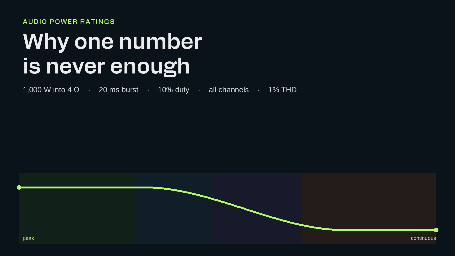
A power rating is a point on a curve: how many watts, for how long, into what load, and across how many channels, all of this needs to be considered. Standards define where that point exists on the curve. However, simply printing a number of watts in a specification is not the same thing as a rating.
A single number of watts is not a power rating. 1,000 W can be a click of a hundred microseconds or a sine wave that runs all afternoon. The voltage can match. The current can match, but the energy, the supply and the heat do not.
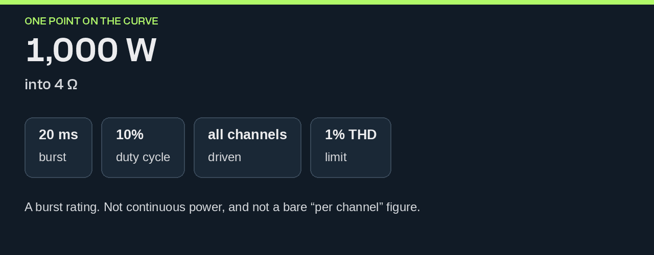
The rating is a point on a curve of available power against time. We can write that point so someone can use it to find it on that curve:
1,000 W into 4 Ω, 20 ms burst, 10% duty cycle, all channels driven, 1% THD.
Read from left to right to see the available power over increasing durations, from microsecond bursts to continuous operation.
The curve
Read available power from left to right, from microseconds out to continuous operation.
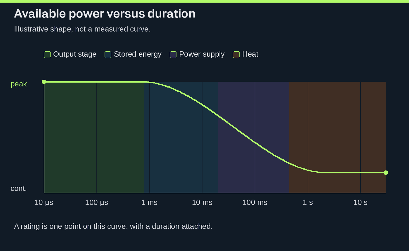
- Output stage. At the shortest times the limit is voltage swing, peak current and the safe operating area of the switches. The supply has not moved.
- Stored energy. From about a millisecond the joules come off local capacitors and the DC bus. Current may still be there while the rail sags.
- Power supply. From a few tens of milliseconds the stored energy is gone. Magnetics, PFC and mains current have to replace it.
- Heat. From about a second, average loss, the heatsink, airflow and junction temperature set what can be held.
One amplifier, one curve. The number you publish is a point on it, and the duration is part of the number.
Peak power is only one part of the story
Into a resistor:

For 1,000 W into 4 Ω:

Those three numbers fix the output stage. However, they do not stipulate how long the peak power can stay at that point. Duration is the next element in our sentence and it’s an important one.
Duration turns power into energy

Hold the same 1 kW and only change the time:
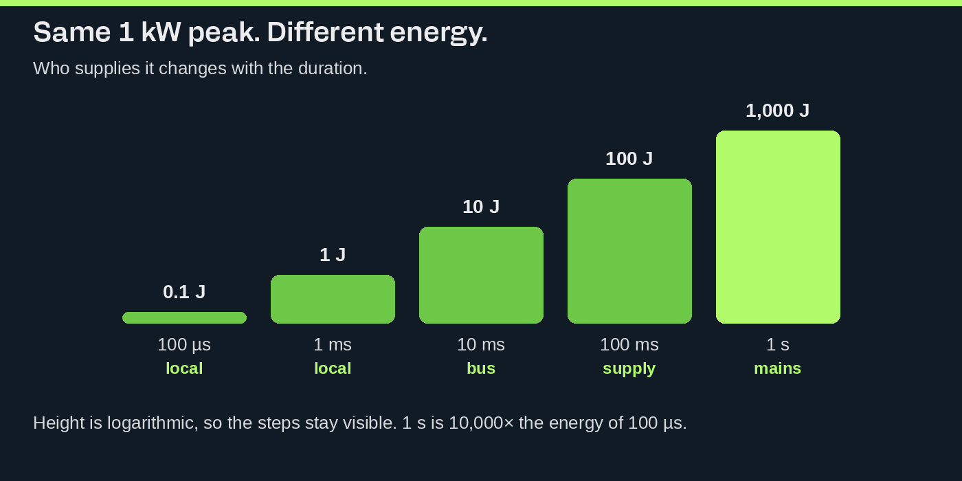
A tenth of a joule can come from a charge already on the board. A kilojoule comes through the mains connector. So the rating names the burst length and how soon it may repeat. Two amplifiers that both reach 2 kW for 10 ms are different products if one repeats every 20 ms and the other needs 500 ms to recover.
On the millisecond scale the energy you can still take from the bus is:

When that difference is spent, the rail falls and the waveform clips, even if the transistors could still switch the current.
Music uses both ends of the curve
Programme material spends very little time at the peak. Crest factor is that ratio, in decibels:

At 1,000 W peak and 12 dB:

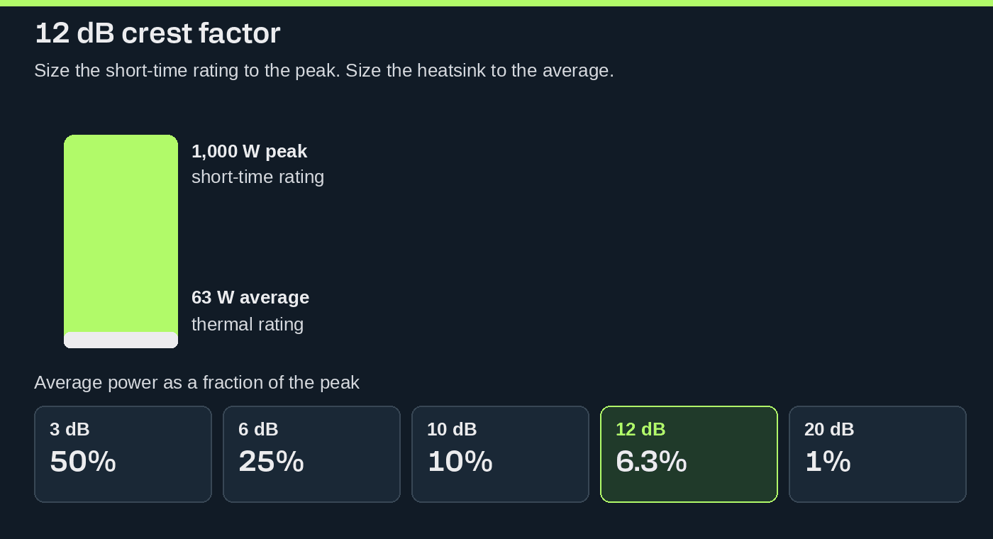
The short-time rating is chosen for the peak. The thermal rating is chosen for something close to that average. A professional amplifier can sit well above its continuous mains rating, because music does not ask for the peak continuously.
A sine wave is the test for the thermal end, not an accurate representation of music content. Its crest factor is only 3 dB, so the average is half the peak. We use it to prove protection, supply and reliability. We do not publish it as the only number and call it the music rating.
The same crest factor can still be a different burst
Crest factor does not say how the energy is arranged in time. Two signals can share it, and share a duty cycle, and still stress the amplifier differently.
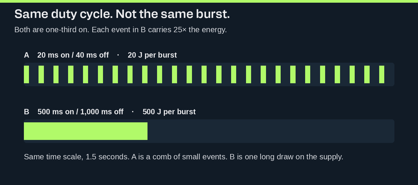
Signal A is 20 ms on and 40 ms off. At 1,000 W that burst is 20 J. Signal B is 500 ms on and 1,000 ms off. At 1,000 W that burst is 500 J. Same fraction of time filled, twenty-five times the energy in one event. The 20 J burst can be a capacitor event. The 500 J burst empties the bus and makes the supply work during the burst.
The burst power rating should state both the burst duration and the duty cycle, e.g how long each burst lasts and how often it repeats. Crest factor is only part of the story, it does not tell you how long the amplifier can sustain that power.
A multichannel amplifier gets three numbers
If a channel multichannel amplifier is capable of delivering 1 kW, that does not necessarily mean that four channels can deliver 4 kW continuously. Each output stage may be able to reach 1 kW, but a shared power supply can limit the total power available when all channels are driven together. This can be a sensible design for audio, where peaks are brief and channels do not necessarily reach their maximum output at the same time.
Three figures worth looking at:
- Maximum power per channel.
- Maximum power when the channels burst together.
- Continuous power with every channel driven.
Power sharing is then a specification, not a hidden limit. The supply has to reproduce the waveform without compression. It does not have to hold a full-scale sine on every channel at once.
The thermal limit comes from losses, not output power
A Class-D output stage delivering 1 kW at 95% efficiency does not turn 1kW into heat.

At 90% efficiency, that rises to about 111 W for the same output. Efficiency varies with output level, load, switching frequency and the devices used. At the continuous-operation end of the curve, what matters is whether the amplifier can keep supplying power while removing the heat generated by its losses.
The test load matters, too
The load stated in an amplifier’s power rating describes the test conditions. A loudspeaker behaves differently from a simple resistor: its impedance varies with frequency and can fall below its nominal value, while its phase angle shifts voltage and current out of alignment.
That means the amplifier may need to supply substantial current even when relatively little real power reaches the loudspeaker. A reactive loudspeaker load can therefore place greater demands on the output stage than a resistive test load with the same nominal impedance.
A meaningful power rating should always state the load used for the measurement.
Standards name the point
There is a standard for amplifier power. It does not fold the curve into one watt figure.
IEC 60268-3:2018, Sound system equipment – Part 3: Amplifiers, is the general standard. It covers analogue amplifiers, and the analogue parts of analogue/digital amplifiers, in professional and residential sound systems. It lists the characteristics a specification should include, and the method for each. It is used together with IEC 60268-1 and IEC 60268-2.
The principle is the rating line at the top of this article:
A power figure means something only when the measurement conditions are part of it.
In 2018 the maximum effective output power was added to the list. The characteristic is distortion-limited at 10%. A result at 1% THD is a different point.
The same standard already separates power by time. Next to distortion-limited output voltage and power, it defines:
- short-term maximum output voltage and power
- long-term maximum output voltage and power
- temperature-limited output power
- the sustaining time of the rated output
Short-term, long-term and temperature-limited are three places on the curve. Sustaining time is the duration. Publish the characteristic under that name. A popular watt number with the name removed is not what the standard asks for.
Into a resistor the conversion is still:
1,000 W into 4 Ω still leaves the measurement unfinished. Frequency, distortion, duration, one channel or all of them, burst or continuous sine, supply conditions: those are the fields IEC 60268-3 exists to pin down.
A continuous reading and a burst reading can both be measured correctly and still disagree. They are different operating conditions. Both belong on the curve.
Other standards cut the same problem differently
ANSI/CTA-2054-2024, *Specifications for Selecting an Amplifier for Use with a Loudspeaker System, defines the test and the report for a maximum rated loudspeaker drive level. It applies to full-range, mains-powered home amplifiers, single-channel and multi-channel, that are not sold as a pair with one loudspeaker. It is not a standard for touring or installed sound. It asks the question "is this amplifier enough for this loudspeaker?" which looks at a measurement, factors in the conditions, it's not a glance at a wattage.
ANSI/CTA-2006-D, *Testing and Measurement Methods for In-Vehicle Audio Amplifiers, is for amplifiers running from a vehicle electrical system. It separates continuous power, dynamic power and maximum dynamic power. In the listings published against that standard, continuous and dynamic power are stated at 1% THD+N, and maximum dynamic power at 10%. The burst shape and the supply voltage belong to that automotive test. Amplifiers for professional audio applications list burst and continuous power separately, with the test conditions clearly stated for each.
A music-like signal is more than a crest factor
Using a sine and a defined burst are the correct ways to measure, provided the test conditions are specified so another test bench can reproduce the measurement. Music varies in level and frequency content, its made up of peaks, spectrum and crest factor.
AES75-2023 measures the maximum linear sound level of a loudspeaker. It is not an amplifier power standard. Its signal is Music-Noise. The spectrum, and the crest factor against frequency, were built to follow music.
A realistic signal is not fixed by one crest-factor number. The spectrum, and where the peaks fall in frequency and time, are part of the load.
That shows up when the amplifier limits, shares a supply, or limits current differently across frequency. A 12 dB noise signal and the 12 dB bursts we mentioned earlier in this article are not the same as this test.
Continuous and short-term, measured as a pair
At AES Convention 144 in 2018, D. B. Keele Jr., Steven Hutt, Marshall Kay and Hugh Sarvis proposed a method that measures both ends, for electronic and electroacoustic systems, power amplifiers included (convention paper 427).
- Continuous maximum output. Broadband, with steady-state signals of low crest factor.
- Short-term maximum output. Narrow-band, with signals of high crest factor.
Low crest factor holds the thermal end. High crest factor reaches the voltage, the current and the stored energy. Neither result is the whole amplifier. The paper is a proposal, not an adopted standard. The pair of numbers is still the pair worth publishing.
A burst is a timing, not a name
Gated sines, including the tests often called EIAJ, are useful because the on time and the off time are defined. The name of the test is not a definition.
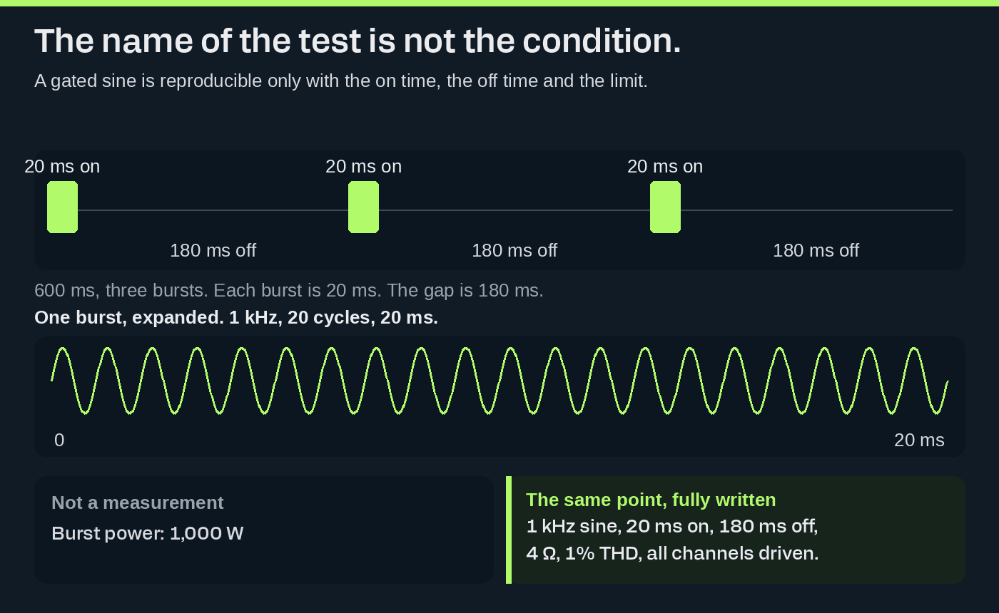
A gated sine answers a power question when these are stated: frequency, on time, off time, repetition period, load, distortion limit, and how many channels were driven.
This can be repeated on another bench:
1 kHz sine, 20 ms on, 180 ms off, 4 Ω, 1% THD, all channels driven.
This cannot:
Burst power: 1,000 W.
A burst power rating should state both the burst duration (how long each burst lasts) and the duty cycle (the percentage of each complete cycle for which the burst is on). Together, these tell you how often the burst repeats.
Once the burst duration is known, the duty cycle determines the repetition period: the time from the start of one burst to the start of the next. A 20 ms burst at 10% duty cycle repeats every 200 ms. The same burst repeated every 100 ms has a 20% duty cycle and, at the same burst power with no output between bursts, delivers twice the energy per second.
This places a different demand on the amplifier, and so is a different point on our curve.
Equal duty cycle can still hide a different energy in each event, as the 20 J and 500 J bursts showed. The timing has to include the length of the event, not only the fraction of time that is filled.
The methods sit on one time axis
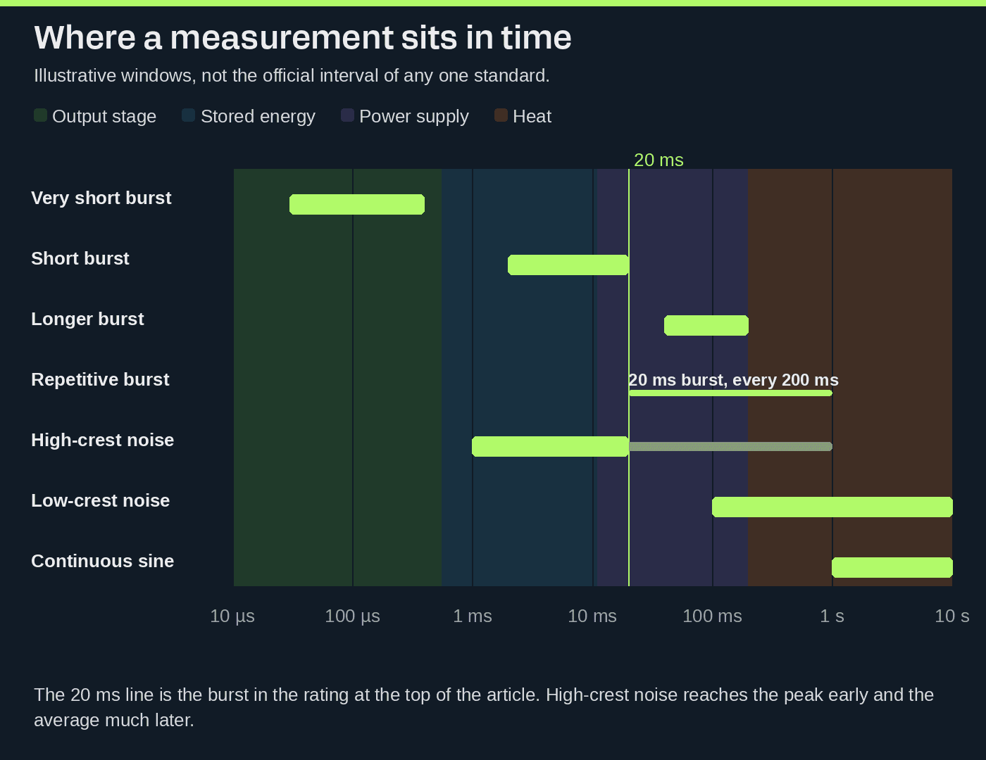
- Very short burst. Peak capability. The limit is voltage, current and the switches.
- Short burst. Dynamic power. The limit is the output stage and the energy stored next to it.
- Longer burst. Energy in one event. The limit is the DC bus, and the supply during the burst.
- Repetitive burst. Whether that burst can be repeated. The limit is how fast the supply recharges.
- High-crest noise. Programme-like peaks. The limit is the balance of peak and average.
- Low-crest noise. High-duty programme. The limit is the supply and the heat.
- Continuous sine. What can be held. The limit is the supply and the thermal system.
The bars are illustrative. Each standard defines its own window. No line is the real power of the amplifier. Each line is a real power, and a different part of the operating range.
What gets published
Three lines, for three regimes. They do not correct each other.
The short-burst rating should state both the test frequency and the burst duration:
1,000 W into 4 Ω, 20 ms burst, 10% duty cycle, 1 kHz, all channels driven, 1% THD.
The continuous point, on its own line. The watts below are an example of how that line is written. They are a different place on the curve from the 1,000 W burst, and they are not a product rating:
Continuous output power: 250 W into 4 Ω, all channels driven, 1% THD.
Programme, separately again:
Programme: shaped noise, 12 dB crest factor, spectrum stated, all channels driven.

Available power is a function of time.
A specification that holds up carries both lists.
Electrical conditions, so someone else can measure it again: load, frequency, output voltage, distortion limit, which channels were driven, supply conditions.
Time conditions, so the number has a place on the curve: peak power, burst duration, energy in the burst, repetition rate, duty cycle, crest factor, average power.
IEC 60268-3 is how the first list stays honest. The curve is the second list. One number and the letter W is neither list.
Power says how hard. Energy says for how long. The rating is both.
Standards and papers
- IEC 60268-3:2018 — Sound system equipment – Part 3: Amplifiers. Used with IEC 60268-1:1985 and IEC 60268-2:1987.
- IEC 60268-1 — Sound system equipment – Part 1: General
- IEC 60268-2 — Sound system equipment – Part 2: Explanation of general terms and calculation methods
- ANSI/CTA-2054-2024 — Specifications for Selecting an Amplifier for Use with a Loudspeaker System
- ANSI/CTA-2006-D — Testing and Measurement Methods for In-Vehicle Audio Amplifiers
- AES75-2023 — AES standard for acoustics – Measuring loudspeaker maximum linear sound levels using noise
- D. B. Keele Jr., S. Hutt, M. Kay and H. Sarvis, AES Convention 144, paper 427 (2018) — Proposed AES Test Standard for Specifying Continuous and Short-Term Maximum Power and SPL for Electronic and Electro-Acoustic Systems: Part 1